Professionals and DIY enthusiasts rely on engineering diagrams to understand what components are included in a system, where these components are located, and how they connect and interact with each other. Understanding a visual representation of a system or a process flow is often easier than reading highly technical text describing the system or process.
Your level of expertise and what you are trying to accomplish will determine which type of diagram you will want to use. For example, a professional electrician may want to use a detailed schematic to track down and troubleshoot problems in an electrical system. On the other hand, if you are replacing a light switch in your kid’s bedroom, the simple pictorial diagram that accompanies the installation instructions is typically all you need to get the job done.
In this article, we will discuss the differences between schematic diagrams and pictorial diagrams to help you determine which type of diagram will be best for your project.
What is a pictorial diagram?
A pictorial diagram uses pictures to represent the different components of a particular system. Pictorial diagrams can vary in level of detail. Some diagrams may have realistic pictures to make the various components easier to identify. Others might have simple sketches that can easily be understood by the average person working on a weekend project.
Let's explore some pictorial diagrams that you may encounter.
Block diagram
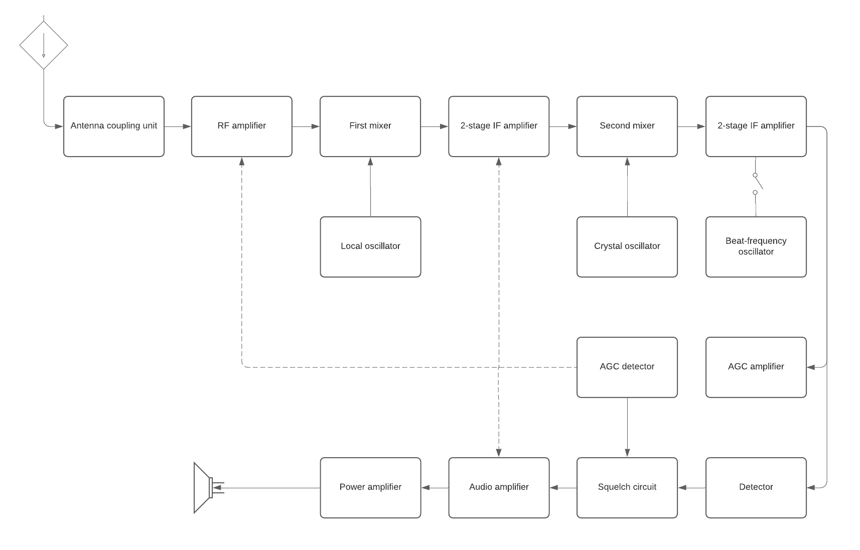
As the name implies, a block diagram uses simple block illustrations instead of standardized symbols or detailed images to represent the main components of a system. Block diagrams are often used in hardware and software design and in electrical engineering. They can also be used to create business data flow charts.
Block diagrams are typically less detailed than other types of diagrams and are meant to give you a high-level overview of a system’s components, the connections between each component, and the relationships between them. The simple labeled shapes make it easier for non-professionals to understand the basic concepts of a system.
These types of diagrams are used to troubleshoot problem areas in existing systems, make initial plans for a new system, and present new ideas.
The following is an example of a block diagram showing the basic, high-level outline for wiring a doorbell chime with front door and back door push buttons. Notice that the diagram is not very detailed, but it gives you enough information to understand how to connect the doorbell buttons to the wires leading to the chime.
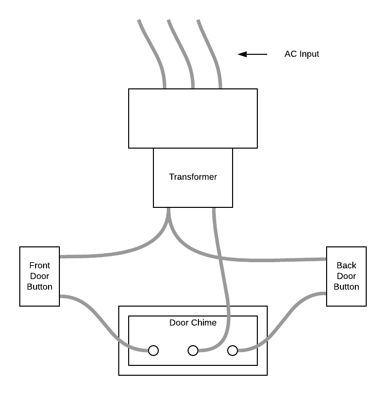
Get started on your own block diagram with this template.